Sunday, March 15, 2015

Arduino Day 3 (Bricktronics)

The Assignment:
We were instructed to begin to apply our base knowledge about the Arduino coding language and capabilities to sciborg robots.

S. O. S. and Functions in Arduino:
before beginning to build or program our sciborg, we had to first figure out how to create a function within arduino so that we don't have to rewrite entire sections of code each time we want our sciborg to perform a task.
This particular program shown above creates and defines the functions dot() and dash() in order to create a simpler pattern that is easily discernible. In this case, the dot() and dash() functions are combined to create the classic S.O.S pattern from Morse Code. 


Building Frank (the Sciborg):
Most of the Sciborg was already built, all we had to do was solder the wires for the battery pack and add that to the board along with our arduino and the Bricktronics LEGO  shield.

Programming Frank:
Task #1: Open and modify Bricktronics "Single Motor" sketch

The sketch below shows the unmodified single motor program provided by Bricktronics. It names the motor m then establishes the rate at which the computer can communicate with the motor. In this case serial.begin(115200) indicates that the rate will be 115200 bps. further down in the code the program tells the motor to move forward then backward at varying speeds.

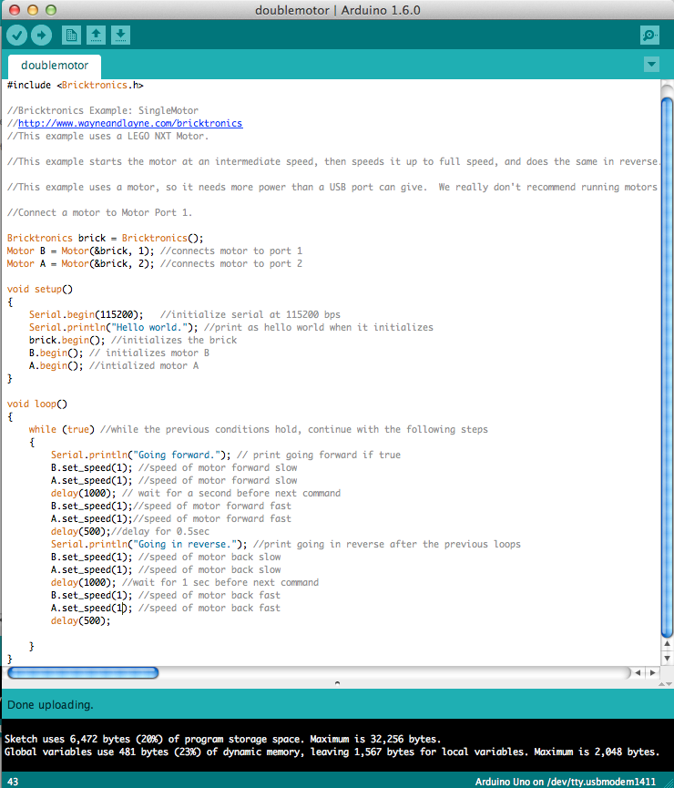
Next we modified the code to include two motors. We also changed the names of the motors to be motor A and motor B which mimics the labeling found on the sciborg.


Task #2:What is the minimum speed the motors will run at

Next we altered the code in order to find out the minimum speed required to get the motor to turn the wheel when it is in contact with the ground. In the sketch below we changed the speed to 0 in order to make sure we understood the speed function correctly before proceeding.

Although we were certain that a speed of 1 would not be enough to make the motor turn even if the wheel was not bearing the weight of the sciborg. As we predicted the wheel did not turn.

After playing around with the numbers, we found that the absolute minimum speed required to make the sciborg wheels move while bearing the weight of the sciborg was around 57. This is with only going straight. I imagine that a larger minimum speed would be needed if additional friction and torque was put on the motor and axel from turning.

Task #3:Hard turn
The first time we wrote the program we simply made one speed negative and the other positive. The resulting motion was for the sciborg to turn with its center of motion being in the middle of the axle. we also found that if one wheel was 0 while the other was 100 then the sciborg would make a hard turn, but this time the center of rotation was the wheel that had a speed of 0.

Task #4: Gentle turn
 Next we changed the program, making one wheel have a speed of 150 and the other a speed of 100. This allowed the sciborg to make a gentle turn since both wheels were turning, just at slightly different speeds.


Task #5: Travel 10 feet and stop
In order to figure out a code to make the sciborg stop at 10 ft, we timed the sciborg traveling 2 meters. We then used the mathematical relationship that states that distance = (speed)(time) to figure out how long we needed the program to delay for, Note that the speed we entered was the speed actually measured when we timed the sciborg, not the speed found in the code.


Task #6: Drive Straight
We found that the sciborg drives straight if the front wheel which is not propelled by a motor is oriented straight. Also, if the sciborg's speed is negative it actually drives straighter than if it is positive. i think that this difference has to do with the structural mechanics of the non-motorized wheel.

Task #7:Motor button sensor
The button sensor uses a feature called "debounce" this feature is needed to help the sensor function properly. It forces the program to check whether or not the button was actually pressed within a short time period. If it was not used then, a single press could be seen as more than one confusing the program.

The task at hand was to make the sciborg respond to the button touch sensor if it is pressed, by stopping, moving backwards in a straight line, then turning before going forward again. Initially, we had trouble getting the sciborg to move backwards in a straight line due to the non-motorized wheel in the front of the sciborg which is attached to a rotating bearing. Our initial code is shown below.


We altered the code to account for the front wheel. We did this by first observing which wheel it favored to turn, then we rewrote the code so that the sciborg could quickly correct itself before moving backwards in a straight line before turning. Our first attempt to correct the wheel,shown below, was unsuccessful because we over corrected.
.


The difference needed to correct the wheel proved to be very small. It only needed a difference of .99 in order to correct the front wheel at the proper angle to move backward in a straight line, 


Reflection:
I think that the biggest thing that I took away from the tasks in this set, was that realities concerning the design and structure of a device must be taken into an account when writing a code. We cannot simply assume that the program will function within a perfect world. We also must expect that unexpected problems will arise due to these imperfections.


Lecture By Professor Robert Wood


I attended a lecture from Robert Wood, the professor of the Harvard school of Engineering and Applied Science. He spoke to us about his work with micro-robots and micro-technology which is an intermediate between nanotechnology and the scale of common technology used in everyday life. He draws inspiration from the natural design of flies and other small insects. The scale of the project brings a whole new set of challenges to his work which include powering the device, programming and assembling it. In order to meet the demands of his work, professor Wood draws on the intelligence of his fellow researchers and students who come from a wide range of fields. 


The images above show how the micro-robots can be constructed from a single piece of material. The material is made from very thin layers that have different cuts that will contribute to the final folding process. The designs are rendered in such a way that if pressure is applied in the proper areas the piece simply pops up into shape. This method replaced his earlier, more time-consuming method which involved individual parts that must be expertly assembled. The new method allows the the robots to be reproduced more quickly and with greater accuracy.


The schematized design above is one of many of the designs used by Wood and his team to identify the mechanics involved in the balance and motion necessary for insects to fly or move in other ways. They utilize the ingenious designs produced by evolution to serve their own needs. As he explained, the wing motion of different flying insects utilize different motion, wing sizes, and wing shapes. The members of his team that possess a background in biology helped to compare and contrast these different methods in order to find the one most compatible for a mechanically designed version.


The micro-robots pictured above are only some of the designs that have been constructed by his lab. Each one is modeled after a natural counterpart which it seeks to mimic in locomotion and general design. 

Professor Wood did not speak much about the possible uses of these little robots, but what he did say was mostly concerned with their ability to work in large numbers to perform a single task. He mentioned that they could be useful in agriculture, but I imagine that their uses in surveillance and other military intelligence tactics is probably of equal if not more interest. 


Monday, March 9, 2015

Arduino Day 2

The Assignment:
We were challenged to go more in-depth with the Arduinos and to further explore the ideas of feedback and control with the programs knob and sweep, as well as create a program that responds to a photo cell.

Sweep:
After showing our final blink patterns, we connected the arduino to a device called a servo, which consists of a lego motor with rotating disk attached to it. The Servo was controlled by a program called Sweep. Below is the base program provided by the arduino site which commands the servo to turn back and forth 180 degrees at a rate of 1 degrees every 15 ms.


Knob:
The knob program correlates the amount the knob, also called a potentiometer, was turned with the blink rate of LED. The base program is shown below. Notice how the range of the potentiometer had to be changed from 0 - 1023 to 0 - 180 degrees to make its units familiar to us.


Photocell Program:
The photocell program that we wrote told the led light to turn on when a certain set value of "darkness" was reached as measured by the lego light sensor.


Reflection:
I am constantly amazed by the complexity of the computer coding language. Each line has a very specific job, that will not allow the program to function properly if it is not written correctly. I found it incredibly helpful to be forced to go through each line and what it does to the program. Otherwise, the lines remain very abstract and indecipherable things.  

Sunday, March 8, 2015

Arduino Day 1

The Assignment:
In order to explore the ideas of Feedback and control, we were challenged to create a code to control a series of LED lights to blink in a pattern, first using the Blink with delay program and then the Blink with no delay.

Relevant Physics:
The Arduino program utilizes a coding software that can control a bread board. Some basic physics concerning Electricity is needed before building circuits. The biggest equation to remember for circuits, is the equation V=IR where V = voltage (volts) I = current (amps) and R = resistance (ohms).  How this equation is applied changes depending on whether the resistors in the circuit are in series or parallel. In the drawing below, the top arrangement is in series, while the bottom is in parallel. 


Step One:
The first step in this process was to see if our arduino would execute the Blink with Delay program using the embedded in LED square on pin 13. This was simple enough since all we had to do was hook the arduino up and upload the program.


Step Two:
Next we experimented with the program by altering the delay times. we found that without a certain amount of time delay, the light would tune on and off so quickly that we wouldn't be able to tell that it was turning off at all. The result is that the light simply looks light it is always on.


Step Three:
We then altered the program so that the LED light would stay on for 2 second (2000 ms) and stay off for 1/2 second (500 ms) so that the blinking pattern was now slow enough that our eyes could register it.


Step Four:
After completing step three, we left in the LED and resistor that was in pin 12 already. We then rewrote the Blink with delay code so that it would make both the LED in pin 12 and the LED built into the board light up in a pattern. The pattern we wanted to emulate was that of a drummer in a 4 beat rhythm pictured below. Each circle denoted the LED is on, the dash denotes that the LED is off. The delay times for each symbol is 250 ms (1/4 second). Notice how we didn't include the last line of the 4 beat pattern since the program will simply repeat itself.
Writing a program for this pattern proved to be more difficult than we initially thought. At first we tried to address each pin separately with its own delay pattern. We found that doing it that way made one pin go and then the next without actually executing the pattern(the defective code is shown below).

We fixed this by grouping the code into delay segments then telling both pins what to do within that delay period. This code functioned how we wanted it to!


Step Five:
After we got our pattern for two LED's to function correctly it was fairly straight forward to rewrite the program to include more pins. We added more LED's and resistors to our bread board in order to create a more complex patter using the Blink with delay program. The pattern we wanted to make this time was scale that traveled up and down the line of LED lights.


At first, only our first two lights would light up brightly, while the others lit up very dimly. At first we though there was a problem with they way we had connected the LED's to the bread board. After playing around with it, we realized that this was not the case. We then looked back through our code and found that the reason that two of the lights wouldn't light up brightly was because we forgot to name the other pins as an output early on in the code.

This video shows how the LED's behave if their corresponding pins are not named as outputs.

 This video shows how the LED's behave once their corresponding pins are named as outputs.

Since we were ahead of the class we decided to make another cool pattern before moving on to the blink with out delay program. Our new pattern used 5 pins and sought to make the lights look as if they were crossing each other.
 The code is as follows...

And her is the video!

Step Six:
Our last challenge of the day was to use the Blink without delay program that Arduino supplies and to rewrite it to include more pins and to create a new pattern. This type of code allows the program to operate on different levels by not suspending the code with a delay. since we are unfamiliar with the language of the code, we had difficulty trying to write more complex codes like the two we did in set five. We tried to Google different codes and tutorials, but many of the tutorials assumed that we would know and understand the code language enough to follow without a thorough explanation.


This is the Blink without delay program only altered to include five pins.

To make the pattern more complex we simply changed the times.


Reflection:
After working with even this simple code, I became distinctly aware that coding language is a complex language all its own. The limit to the patterns we were able to create depended on our knowledge of the coding language, much of which we did not know. It was also apparent that when writing code, one must be acutely aware of the details involved so as not to make a small error that could prevent the entire code from functioning correctly.