Saturday, February 28, 2015

Lego Racer

The Assignment:
The challenge was to design a lego vehicle that is propelled by one PicoCricket motor. The vehicle must carry a 1 kg weight as fast as possible on a 4 meter straight, carpeted track.

Gear Train Practice:

Before beginning our lego car design, my partner and I worked on creating lego gear trains in order to understand the mathematics behind gear ratios/gear reductions and to get a feel for how to build with the lego pieces. The gear train pictured above has a gear reduction of 27:1. This value was found by multiplying the gear ratios together. As a class we talked about the advantages and disadvantages of different gear reductions. The higher the gear ratio, the more torque the motor and the less speed the motor has. Conversely, the lower the gear ratio is, the faster the car and the less torque the car has. Depending on the intended function of the vehicle speed or torque could be more or less important. The ultimate decision must be made with cost-benefit analysis in mind.

Design Process:
The first step in our design process was to create a gear train that would fit the needs of our race car. We built a few different gear trains and connected them to the motor. We then determined the gear ration and observed how well these gears turned. We determined from this process that a 15:1 gear reduction (pictured below) would be best for our purposes.

Once we had decided on this particular gear train we began to consider the design of the entire car. We decided that a car with a 3 wheel design would be better than a 4 wheel design because it would reduce the amount of area of the car interacting with the carpet, and reduce weight, thereby reducing friction. We also decided to construct a car that had a lateral axis that was in a wedge or angled shape. This would evenly distribute the 1 kg weight between the two wheel axles and prevent one from bearing so much weight that it would bow and not be able to turn. 


Now that we had our basic deign ready, one of the biggest challenges was how to fit the wheels and motor components to the gear train without interfering with any other pieces. While building we were constantly forced to consider the order of assembly that would be most efficient, since in order to replace one piece, we often had to take apart half of the entire car. 
 

Now it was time to test! The video below is one of our first test runs of the car. What I failed to catch on camera was that the first time that we lined the car up on the line, with the front being the single wheel, the car started moving backwards! Apparently, the motor's direction had been switched. At first we thought that it would be best to switch it back, but we found that the car actually went faster when it traveled with the two wheeled axle as the front. I think that this has a lot to do with the balance of the car. The double wheeled axle in the front allows the car to move along a straighter path, and therefore faster path, since each wheel reinforces the stability of the other. Also, the 1 kg mass is resting over top of the double wheeled axle, but because of the angle of the car it is distributed to the single wheel. This design is even better when the single wheel is in the back because it decreases the static friction present on the front wheel, that would otherwise hinder its initial motion.  


Final Design:

The Race:

 
Engineering Analysis:

As I briefly stated above, the goal of our car was to maximize the power output of the car by finding the median torque and speed of the system. The motor which we were supposed to use has a lot of speed, but very little torque, so we had to design a gear train that would increase the torque enough so that the vehicle could carry a 1 kg mass as fast as possible. Our final gear reduction ended up being 15:1. This gear reduction  proved to be very successful since we one the race!

After the race we talked a little about the effective gear ratio versus the gear train ratio. We found that the diameter of the wheels used can greatly affect the effective gear ratio. Our wheels had a diameter of 8 cm. Since (angular velocity)(r) = Linear Velocity as the radius of the wheel increases its linear output from the angular velocity produced by the motor and gears increases as well.

We also talked briefly about the importance of considering the strength of the materials used and the friction associated with them. In the case of the car, it was important to remember that the axles are made from plastic, which will bend under significant weight. In order to ensure that our axle bent as little as possible, we moved them closer together so that the weight of the car and the 1 kg mass would not be concentrated at the ends of the axle. We also discussed friction as it related to the wheels of our car. As we suspected, the fewer wheels that are in contact with the ground, the less friction. It is also important to distinguish that wheels interact with the floor through static friction, not kinetic friction since they are rolling along the road not sliding. The coefficient of static friction for a given surface is always higher than its kinetic friction.

Reflection:
This project has helped me to grasp the concept of gear trains and the relationship between torque and speed. It also helped me to realize that there are many more things to consider when designing a real world object as compared to the simplified mathematical model. In the case of the cars, we needed to consider not only the gear ration, but the diameter of the wheels, the bend of the axle, the balance of the car, and friction between the gears themselves and between the wheels and the floor.


Tuesday, February 24, 2015

Mechanisms

The Assignment:
Before beginning work on our Lego race cars, the class was instructed to investigate different kinds of mechanisms and how they convert one kind of motion into another, and more specifically how linear rotation can be converted into rotation motion and vice versa. In order to investigate these mechanisms we explored the Cornell's KMODDL or Kinematic Models of Design Digital Library. http://kmoddl.library.cornell.edu/index.php

Reciprocating Rectilinear Motion:
The mechanism which I found to be most compelling was the reciprocating Rectilinear Motion design. It's design is a compact and ingenious way to convert rotational motion to linear motion. A video of this mechanism is linked below.


How It Works:
The Reciprocating Rectilinear Motion Mechanism utilizes the relationship between simple harmonic motion that connects constant rotational motion to that of springs and linear motion. Ideal friction-less springs can be used to interpret this kind of motion through the equations F = kx (where F is the force on the mass of an object, k is the spring constant and x is the distance from the equilibrium position) Since F = ma we can derive the acceleration of the spring. Thus a =(kx)/m As a consequence of this, As the mass approaches the equilibrium position the speed increases until it reaches its maximum through the equilibrium position, As the mass gets closer to the maximum displacement position the velocity approaches zero and instantaneously goes to zero before changing direction. This motion is pictured below is known as a linear restoring force.

If the displacement of the mass on a spring can be represented mathematically as a sine curve which is derived directly from a circle. As we can see from the picture below, the displacement of an object form the x axis follows the circumference of a circle. 

The Reciprocating Rectilinear Motion Mechanism uses this mathematical relation ship and takes it one step further by incorporating a gear system that converts the linear motion contrived from the simple harmonic nature of the rotational motion and then converts that motion into another linear motion perpendicular to the other. The partial gear at the bottom has the same radius of curvature as the wheel above allowing the lateral piece to move with a 1:1 ratio.


Potential Applications:
This kind of mechanism would be useful for something that wants to convert a constant rotational velocity of the disk to a varying linear velocity that reaches its maximum at the linear portions highest displacement. Things such as variable speed saws, that need to accelerate quickly upon each stroke would require this kind of mechanism.

Sunday, February 22, 2015

Well Windlass

The Assignment:
For this next project my partner and I had to build a model of a well windlass that can span a well of 12 cm and lift the cap of a 1 liter bottle of water at least 10 cm from the top of the table. This must be done using a sheet of delrin with a total surface area of less than 500 cm^2 that is either 1/8 in or 3/16 inches thick.

Brainstorming:
Before putting pen to paper I thought about mechanisms that I see in my everyday life that function similarly to a windlass and what makes them effective. Since I swam in high school and worked as a lifeguard for two summers, the thing that stuck out in my mind was the mechanism that is attached to the end of a lane line that is capable of cranking the lane line until it is taught. As well as the giant spool that was used to take the lane lines out of the pool entirely. I also considered how the tuning pegs of a stringed instrument make the strings wind around the pegs until they too are taught and thus tuned properly. With those two designs in mind my partner and I set about generating designs. We decided that a wheel/spool in the center would be best. We added lateral pegs so that the user wouldn't have to crank so many times to get the bottle to rise by increasing the circumference that the wire must travel with one crank. We also decided that a triangular upright would be stronger than a square upright. We also added lateral supports to ensure that the structure could support the weight without wobbling or breaking.

Test Pieces:
 
To prevent unnecessary iterations, my partner and I created a test piece to check the fittings of all the bushings, pegs, notches and holes with varying dimensions. 

 
As you can see, even our test pieces required 2 iterations! The first time that we converted the file into the program used by the laser cutter it cut, but didn't cut deep enough into the delrin in order to cut all the way through the sheet of delrin. After our second cut we were able to figure out the appropriate measurements for both tight and loose bushings as well as the notches and pegs. From there we adjusted the measurements of our main pieces.

Assembly:


We took our paper design then drew it in solid works. From there we printed it out and assembled it. Our main attachment methods for this project were press fitting. Originally we thought that we would need to piano wire the lateral axis to the reel, but because our press fit was so tight, the piano wire proved to be unnecessary. A similar thing happened with the four rods which connect to the edges of the reel. Originally we thought that we would need to heat press them, but we found that our press fitting was tight enough that, that too was unnecessary.


Testing:
Once we tested this design we found that it was sturdy and was able to reel the bottle 10 cm above the table top, as was specified on the hand-out. We did find the adding the handle to the crank made the whole structure want to slide around on the table. Once we took that off it was better, but the windlass still slid on the table top since the table and the delrin are both slick surfaces. In order to address this issue we created prongs that extended from each leg and hugged the table (pictured below). This way the windlass wouldn't slide and have the danger of having one of the legs fall in the opening. This was a major improvement to our design and contributed greatly to its success on presentation day!


Accounting for Materials:

Windlass:
Piece
Quantity
Area of component (cm2)
Total Area (cm2)
Upright
2
115.74
231.48
Disk
2
35.94
71.88
Crank Handle
1
16.71
16.71
Lateral Supports
4
26.26
105.04
Bushings
5
0.71
3.55
Rod (support)
4
5.84
23.36
Rod (central)
1
26.16
26.16

Total Delrin used: 428.66 cm2
Total Delrin rod: 49.62 cm * we had 5cm of total extra length on the ends of the axle which we chose not to cut off.

Additional Pieces for Stability:
Piece
Quantity
Area of component (cm2)
Total Area (cm2)
Hook
4
22.92
91.68
H connectors
8
3.11
24.88

New Total of Delrin used: 545.22  cm2
*We chose to create the prong pieces rather than reprint the entire upright in order to save delrin, however if we had printed the 2nd iteration of our uprights to include that then we would have had a total delrin usage of 502.66  cm2, which only exceeds the limit by 2.66  cm2.


Engineering Analysis:
There was a lot of geometry related design elements which increased the success of our design. The triangular uprights were stronger than a square base design, but less strong than an arch would have been, We chose however to do a triangle because it saved delrin. Also, we realized early on that if the string were to wire around only the delrin rod, it would not be able to bear the weight and that it would take very long to wind up. Therefore we added a reel to the main turning axle which increased the amount of string taken up by a single rotation. This reflects the relationship between linear and angular velocity.

angural velocity = (linear velocity)/(r from the center)
so as the length of the radius increases so does the linear speed reflected by the increased take up in string.

Torque = Frsin(theta)
This equation is relevant to our crank because as the length of the crank increases, the less force is needed to exert the same torque on our axle in order to rotate it. This however must also be considered with the canteliver beam equation


As with the bottle opener, E (Young's Modulus) is constant since the material used was delrin. We also cannot control F since we cannot tell what force the user will put on the handle For the purposes of this analysis I will assume that a reasonable amount of force capable of a normal person is being applied to the bottle opener. That leaves only L and I for us to consider in our design. In the Equation, L is raised to the 3rd power, while I is in the denominator. This suggests that as the L (length) of a design with a given I increases, the deflection of the design increases exponentially. Also, this suggests that as the I of a design with a given L decreases the denominator gets smaller allowing the numerator to get much larger. Based on this mathematical reasoning a shorter length and larger I would give the lowest deflection. Which is what we want!

If this is applied to the central delrin rod axle though, we now can control the F since F = (mass of the bottle)(gravitation contstant or 9.8m/s/s)


Reflection: 
After watching the presentations of all the windlasses in our class, I was struck by how each one was so different that the others. It also stuck me that each design had elements that were ingenious, and other elements that could use further tweeking. This has made me realize that in the real world of design and engineering working in groups and reviewing each other's designs is extremely important. The other person might just have an idea that would make your design that much more effective and efficient.

I also learned the value of creating an efficient test piece which will prevent unnecessary iterations, By making sure that all the measurements would work, we were able to only do one iteration of our main design with only one added feature.

Monday, February 16, 2015

Fastening & Attaching

The Assignment:
In order to successfully construct our next project out of delrin,we needed to learn how to fasten and attach delrin to create both fixed and movable joints. A description of each method, as well as its advantages and disadvantages are below.

Piano Wire:
The piano wire method attaches two pieces by drilling a hole through the first 3 sections of the staggered pieces of the hinge, making sure that there is enough separation between them to allow the hinge to bend. Next we used a slightly smaller drill on the last prong so that the wire would be secured. We then used the press to push the wire into the last prong. This created a hinge that was both secure and easily bendable. The main advantage of this method is that it allows for the creation of movable parts. It is also useful because you don't need to measure the drilled portion out in solid works. A down side to this method is that if the hinge is much longer than the one pictured above, then the drill press won't be able to reach the entire way, to the last prong.

Heat Staking:
 
The heat stake, pictured above, is a very useful piece of equipment to use when attaching two pieces of delrin together. In this process, one first creates a two parts, one that has a hole or notch while the other has a peg that protrudes past the hole's surface. The machine head is heated to about 450 degrees Fahrenheit before it is pressed onto the peg. The pressure and heat fuses the two pieces together by melting them together to form a smooth bump in place of the peg and hole. The advantages of this method include it's permanence. Once fused the pieces are very well, and permanently attached. Also, the heat stake leaves a smooth bump rather than a sharp edge which would be useful in building children's toys or other things that shouldn't have sharp edges. The largest draw-back to heat staking is that once the delrin is fused, there is no way to get it apart without breaking it. This means that in order to repair anything underneath the heat staked pieces would be impossible without breaking those pieces. Another advantage of the heat stake is that the tolerances of the material and the exact fit of the peg and hole is not as essential as with the notch and peg method. I also tested the heat stake on a piece of delrin rod and a flat piece of delrin. Professor Banzaert and I weren't sure whether or not this would work since the rods actually have some glass in them and therefore would have a higher melting point than the delrin sheets. Despite these concerns, the method seemed to work well, and could be of use to my partner and I when constructing our windlass.

Notches & Pegs:
Like the heat staking method, this method involves two parts. One part that has a hole or notch, while the other has a peg. The peg, or edge of the part is then fitted tightly into the hole or notch of the other part. This method is useful because it offers a tight fit between two pieces without making them impossible to separate. This allows the pieces to be taken apart to allow for repairs or upgrades. One draw back of this method is that very small discrepancies in a part's dimensions could produce a part that either doesn't fit at all, or is too loose to be of any structural value. Given that the margin of error is already rather small, it doesn't help that there are often slight differences in the measurements of part made on solid works and the actual part that is cut. This is discussed more below.

Tolerances of Notches & Pegs:
In class we were given two sheets of delrin that had many holes for their respective pegs with slightly varying dimensions to show just how small the margin of error between a tight fit and one that was too loose or too small. We used the digital calipers to measure the dimensions of both parts. We found that the dimension that corresponds with the width of the delrin sheet was more important than the length of the opening.

1) Single Peg and Hole Measurements:
peg thickness: 3.13 mm
too tight:  <3.14 mm
perfect fit: 3.14 mm - 3.17 mm
too loose: > 3.2

2) Double Peg and Hole Measurements
peg thickness: 3.20 mm
too tight:  < 3.21 mm
perfect fit:  3.21 mm - 3.24 mm
too loose: > 3,24 mm

Discrepancies between Solid Works and the Actual Part:
Solid works.....vs.....actual measurements
.135 in.....(.145 in) (.1455 in) (.1435 in)
.125 in.....(.135 in) (.134 in) (.134 in)
.115 in.....(.1285 in) (.1185 in) (.119 in)

As you can see from the chart above, the actual measurement of the part can differ greatly from what is displayed in solid works. This could lead to frustration if not addressed in the testing stage of a design. Having done this exercise, I will make sure that from now on I test out the measurements on solid works versus the real thing to ensure that they fit together properly before cutting out a final piece.


Rods & Bushings:
      

The process of creating bushings for rods is almost identical to that of the notches and pegs method described above, except that it deals with a round opening and a rod with a predetermined diameter, Depending on the purpose of the bushings, the builder may want them to either be fitted or loose. A fitted bushing may be desired if the bushing is at the end of a rod and is meant to hold other moving pieces or the rod in place. A loose bushing may be desired if it is part of a larger moving part or is acting as a buffer between two parts. Bushings are extremely useful for securing rods and the parts connected to the rod, and like the notches and pegs they can be made tight enough to be of structural use without being impossible to dismantle.

We were also instructed on how to operate the band saw in order to cut our rods the appropriate length. This is useful because it is quickly at hand in the We-Lab and can be easily measured without worrying about whether or not it fits

Tolerances of Rods & Bushings:
As with the Notches and Pegs method, the bushings must have a diameter that falls in a rather small range. The difference between a fitted and loose bushing is so small that it is not discernible upon initial observation.

1)Measurements
diameter of the rod: 6.33 mm
tight fit: 6.46 mm
loose fit: 6.66 mm

Reflection:
Learning how to fasten and attach pieces of delrin was a very important first step in the process of designing our windlass. We can now informatively consider all the methods and choose the best one for that particular joint. I also learned that the dimensions that are set on Solid Works are not the same and thus it is very important to create test pieces before the final is cut.

Sunday, February 15, 2015

Bottle Opener

The Assignment:
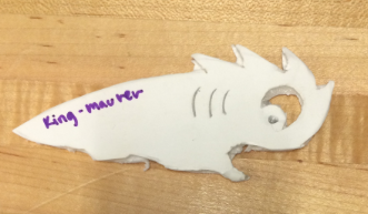
For our first project my partner Helena and I had to design and build a bottle opener from a single piece of delrin using the laser cutter. 

Brainstorming: 

In order to generate ideas, Helena and I first thought about what typical bottle openers look like and what about their design enables them to open a bottle. From there we generated ideas for bottle openers that were creative and funny  to set them apart from the typical bottle opener, but still retain function, After we had chosen our top ten designs, we talked about the possible draw backs of each design. We ultimately decided that a lever design as opposed to a ledge design would be best. Our reasoning behind this was that the delrin would be stronger if the force applied to it was not applied in such a way that it could bend along its plane. If the force is exerted perpendicular to the plane then the cross sectional area is decreased which produces a large deflection. Also, we believed that a ledge design would not provide enough leverage on the bottle cap without extra prongs to grab the bottle, which was not feasible with a 2D sheet of delrin. Thus the lever design would increase the cross sectional area and be less cumbersome to use.


Next, we redrew our favorite design. We measured the height and distance of the bottle cap to ensure that it would fit the bottle top properly. We included the wavy lines at the bottom of the bottle opener, to provide a comfortable and natural grip for the users hand. Each valley corresponds with a finger that would grip it. We thought that this would allow the user to easily grip the piece. The round part on the head of our bottle opener is meant to concentrate the downward force on the center of the bottle cap as a sort of fulcrum that the hook could pull against when upward force was applied.

Iterations:


Next we cut out a foam core model of our bottle opener to ensure that it fit properly over the bottle cap. since our design has many curved lines, it was very difficult to cut out. Upon inspecting our foam core, we decided that the areas that the bottle opener was most likely to fail would be at the hook, or in the thin area created by cutting out a place for the eye. With this in mind we set out to draw our design on Solid Works.


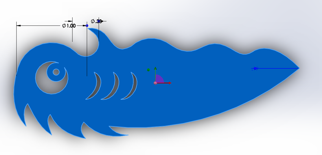
After inspecting our foam core model, Helena and I went to Solid Works to make a drawing that could be used by the laser cutting software. Our first iteration of our design (pictured above) proved to be unsuccessful. I was not present when this design was cut by the laser cutter, but Helena said that she had quite a bit of trouble getting the scale to convert correctly to the computer hooked up to the laser cutter. As a result, the entire piece was about a centimeter shorter than the dimensions we chose in solid works. The shortened piece did not allow the head of the bottle opener to make contact with the top of the bottle cap in the center as was needed. The hook was also too small and too thin to support the amount of force necessary to open the bottle. We also realized that changes were needed in order to make the bottle opener more comfortable to hold. The wavy portion on the bottom proved to be helpful as we expected, but the valleys were not large enough because of the change in scale. Also, the 4th spike on the back of the bottle opener's head dug into my hand when I tried to open a bottle with it. 


In order to fix the problems we encountered with our first iteration, Helena and I went back into Solid Works. First we rounded the tip of the hook and thickened it to give it added strength and durability. With a rounded tip the force is more evenly distributed on the piece rather than on the point, therefore decreasing the likelihood that the piece might chip off like in the first iteration. By thickening it we increased the cross sectional area and therefore decreased the deflection on the hook, making it more durable and strong.  Next we moved the rounded head of the bottle opener out about half a centimeter to make sure that the fulcrum point hit the bottle cap in the center. We aslo eliminated the last spike on the back of the bottle opener's head and rounded the third one to ensure that the user's hand wouldn't be punctured like mine was by the first iteration. Lastly, we added a small hole at the tail of our bottle opener to make it easily attachable to a key chain. 

The Moment of Truth:
 VS. 

This final iteration proved to be successful! It easily opened the bottle, while being comfortable for the user and amusing in its design!

Engineering Analysis:


Cantilever Beam Equation


deltaB=deflection
F=Force
L=Length
E=Young's Modulus (material stiffness)

I=Area moment of inertia (stiffness of cross-sectional area)

Using this equation which models the physics behind cantilevers often found on bridge sites. We can explore the physics behind a successful bottle opener. The goal of a successful bottle opener would be the lowest deflection possible for that material. E (Young's Modulus) is constant within the context of this assignment since the material used was delrin. We also cannot control F since we cannot tell what force the user will put on the bottle. For the purposes of this analysis I will assume that a reasonable amount of force capable of a normal person is being applied to the bottle opener. That leaves only L and I for us to consider in our design. In the Equation, L is raised to the 3rd power, while I is in the denominator. This suggests that as the L (length) of a design with a given I increases, the deflection of the design increases exponentially. Also, this suggests that as the I of a design with a given L decreases the denominator gets smaller allowing the numerator to get much larger. Based on this mathematical reasoning a shorter length and larger I would give the lowest deflection. 

However, this fails to take into account that the user of the bottle opener must have enough material to grip properly and apply force to. It also fails to account for the fact that the type of force being applied to the bottle opener is a kind of Torque modeled by the equation Torque = Fr where F is the force perpendicular to the radius (r) from the fulcrum point. As shown by the equation as the radius increases the Torque increases even if the force does not. 


when both of these equations are considered, I believe that our design is the optimal compromise between the appropriate length and (I) of our design to allow the user to apply a reasonable amount of force, while not compromising the structure of the design caused by a high deflection.

Reflection:
This project was a valuable learning experience in many ways. One thing I  learned was that being able to do multiple iterations is very valuable when addressing a problem. Multiple iterations is valuable because often drawings or even foam core cannot show me how the part will actually behave once it is made. This way, unforeseen problems can be addressed and corrected before the final iteration. I also found it useful to see the actual effects of the physics behind the part manifested in the design. Small changes in dimensions of angles can severely alter the physics and thus alter the effectiveness of a design, Lastly, I learned the basics of solid works and how to prepare a drawing for the laser, both of which can be finicky processes.